Cell News 3/2013
17
RESEARCH NEWS
homogeneity attracted cells from each side and brought them
into direct contact. The orifices themselves being too small
for a cell to pass, thousands of highly ordered pairs were thus
created along the whole membrane area (14). Between this
pairing step and the following electrofusion, excess cells A and
B not bound to an orifice could be washed away, constituting
a mild form of sorting for the prospective fusion products AB.
Fusion was evoked employing dc pulses. Due to the insulating
membrane, the maximum electric field strength of each pulse
again occurred at the contact area of both cells. After the pul-
sing, the cells were dielectrophoretically kept in the traps for
a while. Movement of nuclei through the orifice was observed.
Subsequent cultivation of the fusion products could even be
performed directly inside the chip. Fusion yields were 90% for
human Jurkat lymphocytes (15), 79% for murine L929 fibro-
blasts and 78% for pairs of human K562 lymphoblasts with
human HL-60 promyeloblasts.
The idea of using mechanical structures for achieving selective
cell pairing was taken up by others who e. g. optimized the
orifice diameters to accommodate different cells and introdu-
ced proteinase treatment of cells before their fusion, thereby
achieving fusion efficiencies of (50 ± 10)% (16). Hamdi added
microstructured electrodes to the mechanical traps. The fuso-
genic pulses could, thus, be applied directly to each trap for
fusing murine B16-F10 melanoma cells. They also developed a
structure with dielectric pillars for pairing and fusion of these
cells (17).
Selective pairing on the single-cell level
First steps in fusion on the single-cell level were carried out
electrically (18) and later by laser (19). One decade later, such
single-cell modules were successfully transferred into micro-
fluidic devices (20). Erythrocytes were trapped optically and
aligned mechanically by means of two micromanipulators
equipped with electrodes. After pulse application, the fused
cells were transported into a post-fusion medium.
In our lab, we used dielectrophoretic field cages (DFC) for
achieving a very precisely controlled fusion, albeit as yet at the
price of sacrificing throughput. In this elaborate combination
of microfluidics and microelectrodes, the electrodes are indivi-
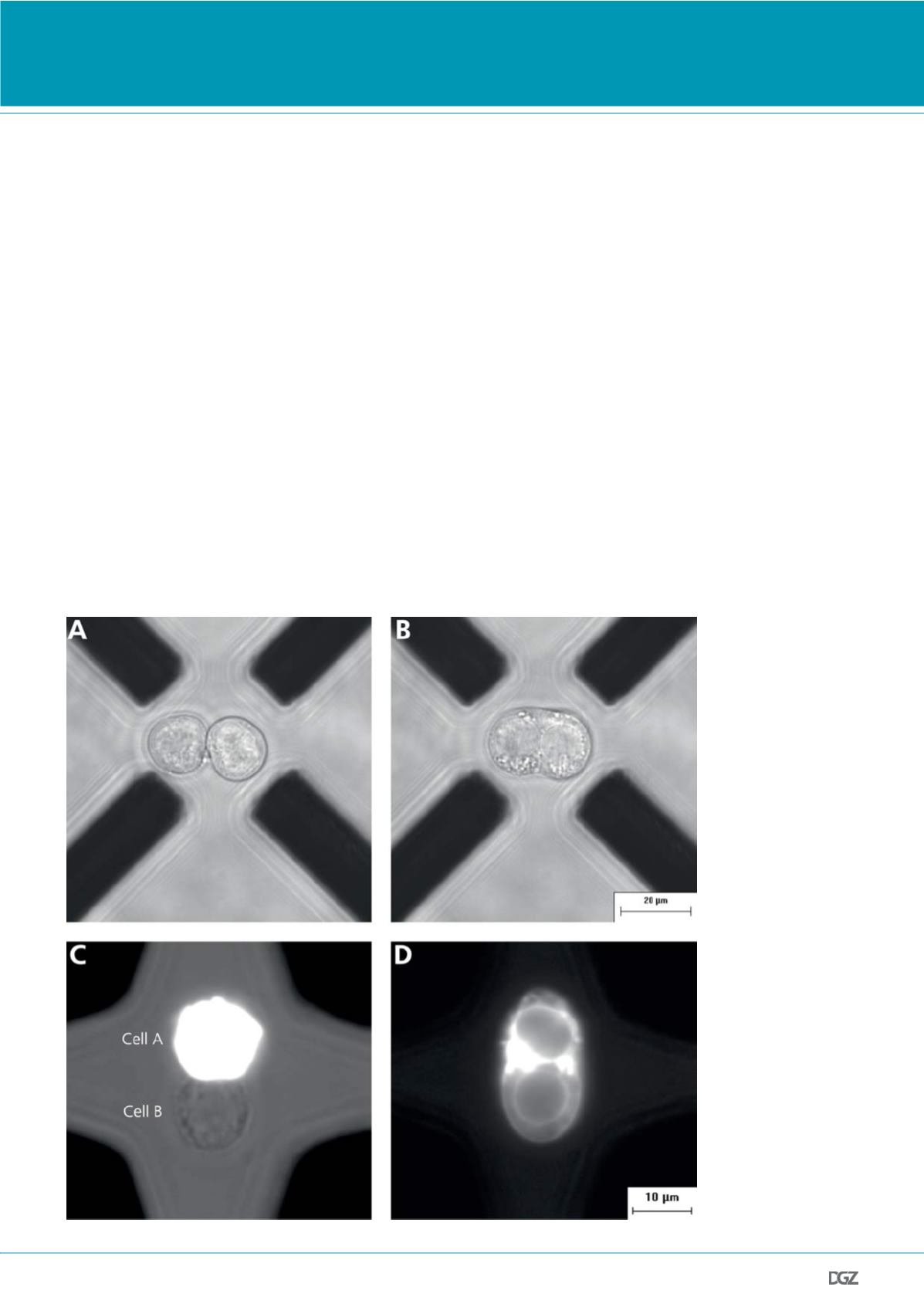
Figure 3. Electrofusion in
a dielectrophoretic field
cage (DFC) consisting of
eight microelectrodes:
(21). Only four electrodes
are visible as black bars,
since two identical layers
are stacked on top of each
other along the optical
axis. The cells are stably
positioned between both
planes. As the cells are in
focus, the electrodes are
slightly out of focus:
(a) Selective pairing under
optimal microscopic con-
trol of individual cells.
(b) Formation of the com-
mon membrane envelope
around both progenitor
cells after fusogenic
pulsing between the
microelectrodes on the left
and those on the right.
(c) U-937 monocytes
paired in a DFC with the
cell A having been stained
with the fluorescent dye
octadecyl rhodamine B
(R18). Combined fluo-
rescence and brightfield
image.
(d) Fluorescence image
after cell fusion. The R18
dye now also stains the
membrane of the former
cell B.


