Cell News 3/2013
16
RESEARCH NEWS
(8). Zimmermann et alii adopted protocols involving consecutive
flushing of the two initial cell populations into the fusion device
and obtained 60% pairing efficiency (9). In general, these im-
provements of the original approach using rather homogeneous
electric fields across the fusion chamber achieved a trapping of
the cells, but no precise positioning or pairing. They also operate
without a post-fusion sorting step, maintaining the advantage
of having a high throughput.
Selective Pairing
The use of microfluidics opened the way for different strategies
towards a selective pairing of the cell types. One option to rea-
lize this is by means of receptor-ligand interaction. In a modi-
fied flow cytometer, appropriately modified cells were coupled
employing the avidin-biotin interaction (10). This enhanced the
fusion yield to 10% of all invested cells. In an analogous ap-
proach, CHO cells were biotinylated before half of them were ad-
ditionally coated with streptavidin and finally both populations
were mixed and flushed through a microchannel with a small
mechanical constriction (cf. Figure 2A). Since the electric field
lines had to pass through this pore, the cells experienced an ele-
vated field strength upon passing it and were fused. For electric
field strengths of 1.2 kV cm
-1
, the fusion efficiency was 30% (11).
Positioning of the cells was also done using structured epoxy
polymer (12). In this case, the polymer covered the electrodes
and the cells were trapped in a size-dependent manner on or in
the structured pits before fusion. Although the corresponding
report does not describe a microfluidic system, the potential of
this set-up for being integrated into a microfluidic environment
is obvious.
An exceedingly elegant idea was published by Skelley and Vold-
man who developed a chip on which two cell populations were
successively trapped in mechanical barrier structures (13). By
using a simple flushing procedure, they could form heterogene-
ous AB pairs with a high fidelity (Figure 2C): first, the cell type
A was flushed into the chip and trapped in the small cavities.
Then, the flow was reversed, moving the cells A into the lar-
ger fusion traps. Subsequently, cell type B was flushed into the
device from the same direction and was, thus, paired with the
cells of the type A. Next, the cell culture medium was replaced
by fusion buffer and the fusogenic electric pulse was applied. As
this set-up also allows for PEG-mediated fusion, a PEG solution
was flushed over the cells instead of the fusion buffer. After the
osmotic stress had induced fusion of the cells, they could again
be flushed out with medium. In this way, electro- and PEG fu-
sion were directly compared, showing a higher efficiency of the
former (80 ± 10)% as compared to the latter (40 ± 10)%.
The Washizu group presented a fusion chip for highly paralle-
lized electrofusion of selected pairs by using a structured mem-
brane as a combined electromechanical trap (Figure 2D): ori-
fices in an electrically insulating membrane locally increased
the electric field gradient. Upon application of an ac field, the
positive dielectrophoretic (pDEP) force resulting from this in-
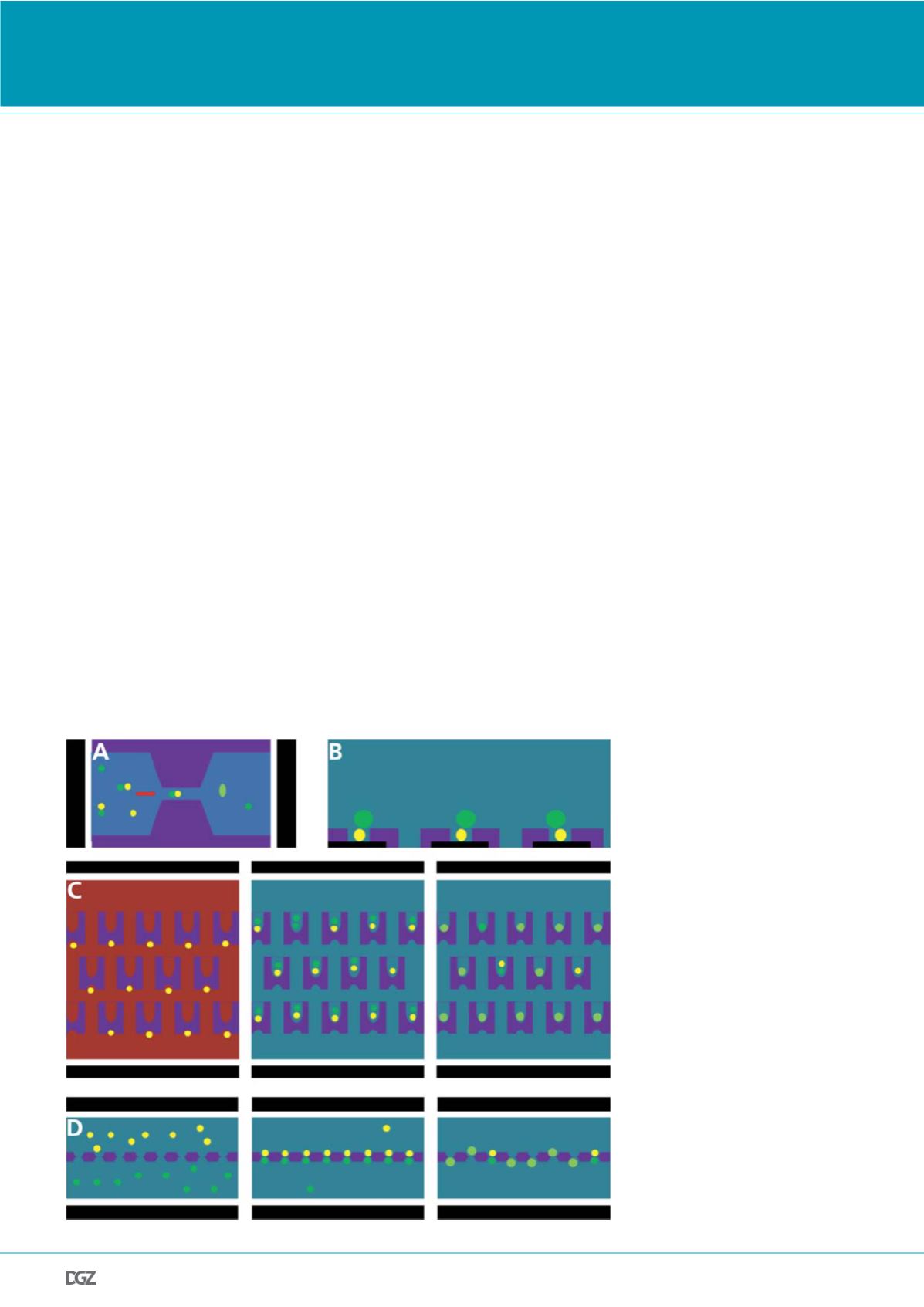
Figure 2. Electrofusion following selective
pairing by means of mechanical barrier
structures:
(a) Cells paired by biotin-streptavidin binding
are flushed through narrow gaps (11). Due to
the electrically insulating properties of the
wall material, dc-induced fusion only occurs
in the gap.
(b) Covering an electrode layer with a polymer
structured into micropits leads to an inho-
mogeneous electric field distribution which
attracts cells into the pits, thus allowing for a
highly reproducible pair formation from cells
of different sizes, depending on both the pit
diameter and polymer thickness (12).
(c) PDMS structures with two different trap
sizes (13). First, individual cells of the type
A are collected in the small cavities from
a flowing suspension. After reversing the
flow, they are trapped in the opposite large
cavities. Then, the cell type B is flushed in the
same direction, trapped and thus paired with
the cell A. Finally, all cell pairs are simultane-
ously fused electrically or by PEG incubation.
(d) A membrane structured with orifices sepa-
rates two chambers with different cell types
on either side (15). The cells are paired and
fused in the orifices by applying an external
electric field. Non-paired cells can be removed
by gentile flushing. The fused cells can either
be harvested from the orifices by applying a
pressure gradient between the two compart-
ments or cultivated directly on the chip.


